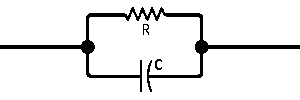
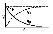
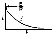
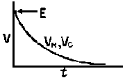
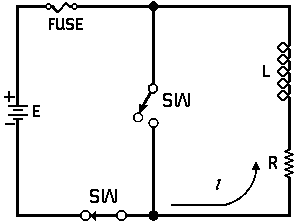
| The formulas whhich follow may be used to closely approximate the growth and decay of current and voltage in circuits involving L, C and Rwhere i = instantaneous current in amperes at any given time (t), E = potential in volts as designated, R = circuit resistance in ohms, C = capacitance in farads, L = inductance in henrys, V = steady state potential in volts, VC = reactive volts across C, VL = reactive volts across L, VR = voltage across R, |
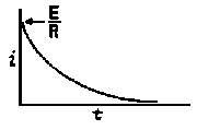
RC = time constant of RC circuit in seconds, L/R = time constant of RL circuit in seconds, t = any given time in seconds after switch is thrown, e = a constant, 2.718 (base of the natural system of logarithms), Sw = switchThe time constant is defined as the time in seconds for current or voltage to fall to 1/e or 36.8% of its initial value or to rise to (1 – 1/e) or approximately 63.2% of its final value. |
|||
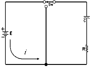
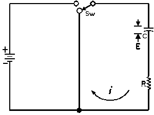
| Charging a de-energized Capacitive Circuit | Discharging an Energized Capacitive Circuit | |||
 |
 |
|||
| E = applied potential. | E = potential to which C is charged prior to closing Sw. |
|||
 |
 |
|||
 |
 |
 |
 |
|
 |
 |
 |
||
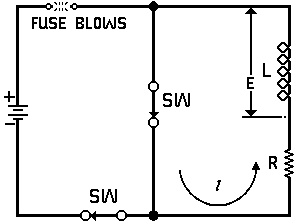
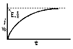
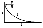
| Voltage is Applied to a De-energized Inductive Circuit | An Energized Inductive Circuit is Short Circuited | |||
 |
 |
|||
| E = applied potential. | E = counter potential induced in coil when Sw is closed. |
|||
 |
 |
|||
 |
 |
 |
 |
|
 |
 |
 |
||
Steady State Current Flow
| In a Capacitive Circuit | In an Inductive Circuit | |||||||||
| In a capacitive circuit, where resistance loss components may be considered as negligible, the flow of current at a given alternating potential of constant frequency, is expressed by |
In an Inductive circuit, where inherent resistance and capacitance components may be so low as to be negligible, the flow of current at a given alternating potential of a constant frequency, is expressed by |
|||||||||
 |
 |
|||||||||
| where | I XC E |
= = = |
current in amperes, capacitive reactance of the circuit in ohms, applied potential in volts. |
where | I XL E |
= = = |
current in amperes, Inductive reactance of the circuit in ohms, applied potential in volts. |
|||


 = 6.28,
 = 39.5,


 =
=

 = 0o
= 0o


