| Resistance Formulas | DIELECTRIC CONSTANTS | |||||
In series  In parallel 
|
Kind of Approximate* Dielectric K Value
* These values are approximate, since true values |
|||||
| Capacitance | ||||||
In parallel  In series 
|
||||||
| The Quantity of Electricity Stored Within a Capacitor is Given by | Self-Inductance | |||||
 where Q = the quantity stored in coulombs, E = the potential impressed across the capacitor in volts, C = capacitance in farads. |
In series  In parallel 
|
|||||
| The Capacitance of a Parallel Plate Capacitor is Given by |
Coupled Inductance | |||||
 where C = capacitance in mmfd., K = dielectric constant, *S = area of one plate in square centimeters, N = number of plates, *d = thickness of the dielectric in centimeters (same as the distance between plates).*When S and d are given in inches, change constant 0.0885 to 0.224. Answer will still be in micromicrofarads. |
In series with fields aiding In series with fields opposing  In parallel with fields aiding  In parallel with fields opposing  |
| Coupled Inductance (cont.) | Resonance (cont.) | |
| where L<subt< sub=””></subt<> = the total inductance,
M = the mutual inductance, L1 and L2 = the self inductance of the individual coils. |
where F<subr< sub=””></subr<> = the resonant frequency in cycles per second, L = inductance in henrys, C = capacitance in farads,  = 6.28, = 6.28, = 39.5, = 39.5, |
|
| Mutual Inductance | Reactance | |
| The mutual inductance of two r-f coils with fields interacting, is given by  where M = mutual inductance, expressed in same units as LA and LO, LA = Total inductance of coils L1 and L2 with fields aiding, LO = Total inductance of coils L1 and L2 with fields opposing, |
of an inductance is expressed by of an capacitance is expressed by  where XL = inductive reactance in ohms, (known as positive reactance), XC = capacitive reactance in ohms, (known as negative reactance), F = frequency in cycles per second, L = inductance in henrys, C = capacitance in farads,  = 6.28, = 6.28, |
|
| Coupling Coefficient | Frequency from Wavelength | |
| When two r-f coils are inductively coupled so as to give transformer action, the coupling coefficient is expressed by, where K = the coupling coefficient; (K x 102 = coupling coefficient in %), M = the mutual inductance value, L1 and L2 = the self-inductance of the two coils respectively, both being expressed in the same units. |
where where |
|
| Resonance | Wavelength from Frequency | |
| The resonant frequency, or frequency at which inductive reactance XL equals capacitive reactance XC is expressed by  also  and  |
where F = frequency in kilocycles. where F = frequency in megacycles. |
| Q or Figure of Merit | Impedance (cont.) | |||||
| of a simple reactor | In series circuits where phase angle and any two of the Z, R and X components are known, the unknown component may be determined from the expressions: |
|||||
 |
||||||
| of a single capacitor |  
|
|||||
 |
||||||
| where | Q = | a ratio expressing the figure of merit, |
where | Z = | magnitude of impedance in ohms, | |
| XL = | inductive reactance in ohms, | R = | resistance in ohms, | |||
| XC = | capacitive reactance in ohms, | X = | reactance (inductive or capacitive) in ohms, |
|||
| RL = | resistance in ohms acting in series with inductance, |
Nomenclature | ||||
| RC = | resistance in ohms acting in series with capacitance, |
Z = | absolute or numerical value of impedance magnitude in ohms, |
|||
| Impedance | R = | resistance in ohms, | ||||
| In any a-c circuit where resistance and reactance values of the R, L and C components are given, the absolute or numerical magnitude of impedance and phase angle can be computed from the formulas which follow: |
XL = | inductive reactance in ohms, | ||||
| XC = | capacitive reactance in ohms, | |||||
| L = | inductance in henrys, | |||||
| C = | capacitance in farads, | |||||
| In general the basic formulas expressing total impedance are: |
RL = | resistance in ohms acting in series with inductance, |
||||
| for series circuits, | RC = | resistance in ohms acting in series with capacitance, |
||||
 |
 = = |
phase angle in degrees by which current leads voltage in a capacitive circuit, or lags voltage in an inductive circuit. In a resonant circuit , where XL equals XC,  equals 0o. equals 0o.
|
||||
| for parallel circuits, | ||||||
 |
||||||
| Degrees X 0.0175 = radians. 1 radian = 57.3o |
||||||
| See page 17 for formulas involving impedance, conductance, susceptance and admittance. | Numerical Magnitude of Impedance . . . | |||||
| of resistance alone | ||||||
| Z = R | ||||||
 = 0o = 0o |
||||||
 of resistance in series, Z = R1 + R2 + R3 … etc.  = 0o = 0o |
 of inductance and capacitance in series,Z = XL – XC  = -90o when XL < XC = -90o when XL < XC= 0o when XL = XC = +90o when XL > XC |
|
 of inductance alone Z = XL  = +90o = +90o |
||
 of inductance in series, Z = XL1 + XL2 + XL3 … etc.  = +90o = +90o |
 of resistance, inductance and capacitance in series   |
|
 of capacitance alone, Z = XC  = -90o = -90o |
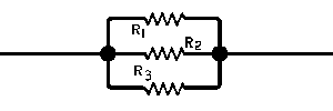 of resistance in parallel,   = 0o = 0o |
|
 of capacitance and resistance in parallel, Z = XC1 + XC2 + XC3 …etc.  = -90o = -90o |
||
 or where only 2 capacitances C1 and C2 are involved,   = -90o = -90o |
 of resistance in parallel,   = 0o = 0o |
|
 of resistance and inductance in series,   |
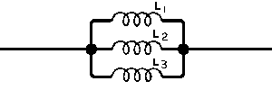 of inductance in parallel,   = +90o = +90o |
|
 of resistance and capacitance in series,   |
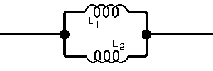 or where only 2 inductances L1 and L2 are involved,   |
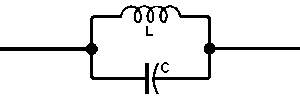 of inductance and capacitance in parallel,   |
|
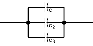 of capacitance in parallel   or where only 2 capacitances C1 and C2 are involved,   |
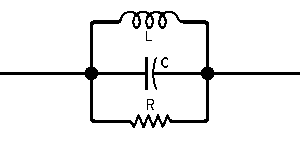 of inductance, resistance and capacitance in parallel,   |
|
 of resistance and inductance in parallel,   |
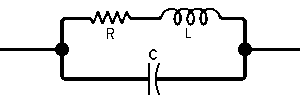 of inductance and series resistance in parallel with capacitance,   |
|
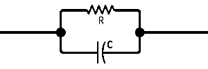 of capacitance and resistance in parallel,   |
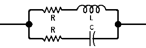 of capacitance and series resistance in parallel with inductance and series resistance,   |
| Conductance | Admittance | |
| In direct current circuits, conductance is expressed by,  where G = conductance in mhos, R = resistance in ohms, In d-c circuits involving resistances R1, R2, R3, etc. in parallel, the total conductance is expressed by Gtotal = G1 + G2 + G3 …etc. and the total current by Itotal = E Gtotal and the amount of current in any single resistor, R2 for example, in a parallel group, by  R, E and I in Ohm’s law formulas for d-c circuits may be expressed in terms of conductance as follows:    where G = conductance in mhos, R = resistance in ohms, E = potential in volts, I = current in amperes, |
In an alternating current circuit, the admittance of a series circuit is expressed by,  Admittance is also expressed as the reciprocal of impedance, or  where Y = admittance in mhos, R = resistance in ohms, X = reactance in ohms, Z = impedance in ohms, |
|
| R and X in Terms of G and B | ||
| Resistance and reactance may be expressed in terms of conductance and susceptance as follows:   |
||
| G, B, Y and Z in Parallel Circuits | ||
| Susceptance | In any given a-c circuit containing a number of smaller parallel circuits only, the effective conductance GT is expressed by and the effective susceptance BT by and the effective admittance YT by and the effective impedance ZT by |


