• Categorie archieven ELECTRONICS DATA HANDBOOK
  • Common-Emitter Amplifier Circuits

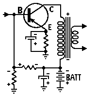
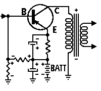
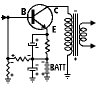
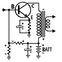
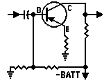
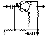
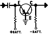
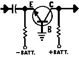
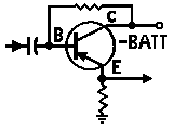
    Using Transistors Only

    In comparing the PNP and NPN circuits this interchange in the transistor, circuits
    shown here, note that the current flow in
    the components of one is completely re-
    versed in the other.  With the vacuum tube,
    this complete interchange of current and
    voltage polarities does not exist.  Because of
    which have no parallel in vacuum-tube
    circuitry can be produced.  Nevertheless,
    the circuits of transistorized equipment are
    still auite similar in many respects to those
    of equipment employing vacuum tubes.
    Using PNP Transistors
    With Positive
    Battery Terminal Grounded
    With Negative
    Battery Terminal Grounded
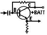
    Using NPN Transistors
    With Positive
    Battery Terminal Grounded
    With Negative
    Battery Terminal Grounded

  • Transistor Amplifier Circuit Configurations

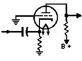
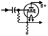
    With Vacuum & Tube Counterparts

    The transistors of primary interest to the exclusively for most amplification purposes
    radio engineer and service technician are
    the PNP and NPN Junction types, whose
    transistor actions are identically alike, ex-
    cept that symbolically, the emitter arrow
    points towards the base in the PNP and
    away from the base in the NPN.  The
    common-emitter circuits are used almost
    as are the common or grounded-cathode
    vacuum tube circuits.  The common-base
    and common-grid as well as common-
    collector common-plate circuits are used
    more for special applications such as
    impedance matching to and from audio
    transmission lines, etc.
    PNP CONTIGURATIONS NPN CONTIGURATIONS VACUUM-TUBE CONTIGURATIONS
    Common emitter–Common cathode.
    Common base–Common grid.
    Common collector–Common plate.

  • Transistor Alpha-Beta Relationships

    Beta


    ALPHA


    1 0.5000
    2 0.6666
    3 0.7500
    4 0.8000
    5 0.8333


    6 0.8571
    7 0.8750
    8 0.8889
    9 0.9000
    10 0.9091


    11 0.9167
    12 0.9231
    13 0.9286
    14 0.9333
    15 0.9375


    16 0.9412
    17 0.9444
    18 0.9474
    19 0.9500
    20 0.9524


    21 0.9545
    22 0.9565
    23 0.9583
    24 0.9600
    25 0.9615


    26 0.9630
    27 0.9643
    28 0.9655
    29 0.9667
    30 0.9677


    31 0.9688
    32 0.9697
    33 0.9706
    34 0.9714
    35 0.9722


    36 0.9730
    37 0.9737
    38 0.9744
    39 0.9750
    40 0.9756
    Beta


    ALPHA


    41 0.9762
    42 0.9767
    43 0.9773
    44 0.9778
    45 0.9783


    46 0.9787
    47 0.9792
    48 0.9796
    49 0.9800
    50 0.9804


    51 0.9808
    52 0.9811
    53 0.9815
    54 0.9818
    55 0.9821


    56 0.9825
    57 0.9828
    58 0.9831
    59 0.9833
    60 0.9836


    61 0.9839
    62 0.9841
    63 0.9844
    64 0.9846
    65 0.9848


    66 0.9851
    67 0.9853
    68 0.9855
    69 0.9857
    70 0.9859


    71 0.9861
    72 0.9863
    73 0.9865
    74 0.9867
    75 0.9868


    76 0.9870
    77 0.9872
    78 0.9873
    79 0.9875
    80 0.9877
    Beta


    ALPHA


    81 0.9878
    82 0.9880
    83 0.9881
    84 0.9882
    85 0.9884


    86 0.9885
    87 0.9886
    88 0.9888
    89 0.9889
    90 0.9890


    91 0.9891
    92 0.9892
    93 0.9894
    94 0.9895
    95 0.9896


    96 0.9897
    97 0.9898
    98 0.9899
    99 0.9900
    100 0.9901


    110 0.9910
    120 0.9917
    125 0.9921
    130 0.9924
    140 0.9929


    150 0.9934
    160 0.9938
    170 0.9942
    180 0.9945
    190 0.9948


    200 0.9950
    210 0.9953
    220 0.9955
    230 0.9957
    240 0.9959


    250 0.9960
    260 0.9962
    270 0.9963
    280 0.9964
    290 0.9966

  • Transistor Formulas and Symbols

    Common Emitter Configuration

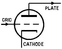
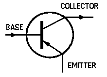
    Transistors can be made to amplify, detect, or to oscillate in much the same
    manner as vacuum-tubes. Shown in the drawings below, is a comparison
    between a triode vacuum-tube and a PNP transistor; where the transistor
    Triode Vacuum Tube PNP Transistor
    base is comparable to the tube grid, the transistor emitter is comparable to
    the tube cathode, and the transistor collector is comparable to the tube plate.
    Transistor Formulas Transistor Symbols
    Input resistance, = Current gain common base
    Ae (Av) = Voltage gain
    Current Gain, Ai = Current gain
      (with Vc constant) Ap = Power gain
    Voltage Gain, B = Current gain common emitter
      (with Ic constant) Ib = Base current
    Ic = Collector current
    Output Resistance, Ie = Emitter current
    Ii = Input current
    Pi = Input power
    Power Gain, Po = Output power
    Ri = Input resistance
    Ro = Output resistance
    The current gain of the common base Vb = Base voltage
    configuration is alpha, where
      (with Vc constant) Vc = Collector voltage
    Vi = Input voltage
    The  current  gain  of  the  common
    emitter is beta, where
    A direct realtionship exists between
    the alpha and beta of a transistor.
      (with Vc constant)            

  • Peak, R.M.S. and Average A-C Values of E & I

    Numerical Comparison Table

    Peak


    R.M.S.


    Average


    1 0.707 0.637
    2 1.414 1.274
    3 2.121 1.911
    4 2.828 2.548
    5 3.535 3.185
    6 4.242 3.822
    7 4.949 4.459
    8 5.656 5.096
    9 6.363 5.733
    10 7.070 6.369
    11 7.777 7.006
    12 8.484 7.643
    13 9.191 8.280
    14 9.898 8.917
    15 10.605 9.554
    16 11.312 10.191
    17 12.019 10.828
    18 12.727 11.465
    19 13.433 12.102
    20 14.140 12.738
    21 14.847 13.375
    22 15.554 14.012
    23 16.261 14.643
    24 16.968 15.286
    25 17.675 15.923
    26 18.382 16.560
    27 19.089 17.197
    28 19.796 17.834
    29 20.503 18.471
    30 21.210 19.107
    31 21.917 19.744
    32 22.625 20.381
    33 23.332 21.018
    34 24.039 21.655
    35 24.746 22.292
    36 25.453 22.929
    37 26.160 23.566
    38 26.867 24.203
    39 27.574 24.840
    40 28.281 25.476
    41 28.988 26.113
    42 29.695 26.750
    43 30.402 27.387
    44 31.109 28.024
    45 31.816 28.661
    46 32.523 29.298
    47 33.230 29.935
    48 33.937 30.572
    49 34.644 31.209
    50 35.351 31.845
    Peak


    R.M.S.


    Average


    51 36.058 32.482
    52 36.765 33.119
    53 37.472 33.756
    54 38.179 34.393
    55 38.886 35.030
    56 39.593 35.667
    57 40.300 36.304
    58 41.007 36.941
    59 41.714 37.578
    60 42.421 38.214
    61 <43.128 38.851
    62 43.835 39.488
    63 44.542 40.125
    64 45.249 40.762
    65 45.956 41.399
    66 46.663 42.036
    67 47.370 42.673
    68 48.077 43.310
    69 48.784 43.947
    70 49.491 44.583
    71 50.198 45.220
    72 50.905 45.857
    73 51.612 46.494
    74 52.319 47.131
    75 53.026 47.768
    76 53.733 48.405
    77 54.440 49.042
    78 55.147 49.679
    79 55.854 50.316
    80 56.561 50.952
    81 57.268 51.589
    82 57.975 52.226
    83 58.682 52.863
    84 59.389 53.500
    85 60.096 54.137
    86 60.803 54.774
    87 61.510 55.411
    88 62.217 56.048
    89 62.924 56.685
    90 63.631 57.321
    91 64.338 57.958
    92 65.045 58.595
    93 65.752 59.232
    94 66.459 59.869
    95 67.166 60.506
    96 67.873 61.143
    97 68.580 61.780
    98 69.287 62.417
    99 69.994 63.054
    100 70.701 63.693

  • Vacuum Tube Formulas and Symbols

    Vacuum Tube Constants
    Amplication factor (Mu or u) is given by
    Dynamic plate resistance in ohms, is given by
    Mutual conductance in mhos, is given by

    Vacuum Tube Formulas
    Gain per stage is given by
    Voltage output appearing in RL, is given by
    Power output in RL, is given by
    Maximum power output in RL which results when
    RL = rp, is given by
    Maximum undistorted power output in RL which
    results when RL = 2rp,is given by
    Required cathode biasing resistor in ohms, for a
    single tube, is given by

    Vacuum Tube Symbols
    Mu or u
    rp
    gm
    Ep
    Eg
    Ip
    RL
    It
    Es
     
    =
    =
    =
    =
    =
    =
    =
    =
    =
    =
    Amplification factor,
    Dynamic plate resistance in ohms,
    Mutual conductance in mhos,
    Plate voltage in volts,
    Grid voltage in volts,
    Plate current in amperes,
    Plate load resistance in ohms,
    Total cathode current in amperes,
    Signal voltage in volts,
    change or variation in value, which may be either an increment (increase) or a decrement (decrease).

    Peak, R.M.S., and Average A-C Values of E & I

    Given Value To get . . .
    Peak R.M.S. Average
    Peak 0.707 * Peak 0.637 * Peak
    R.M.S. 1.41*RMS 0.9*RMS
    Average 1.57*Average 1.11*Average


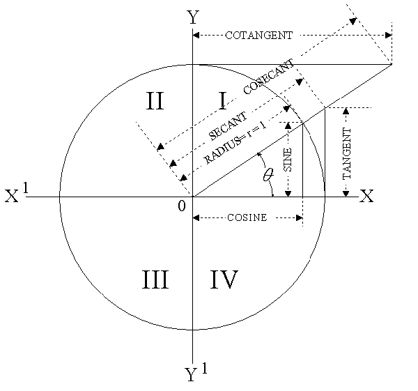
  • Numerical Relations of Angle Functions

    Angle sin Cos Tan Angle o Sin Cos Tan
    0o .0000 1.0000 .0000 45o .7071 .7071 1.0000
    1o .0175 .9998 .0175 46o .7193 .6947 1.0355
    2o .0349 ..9994 .0349 47o .7314 .6820 1.0724
    3o .0523 .9986 .0524 48o .7431 .6691 1.1106
    4o .0698 .9976 .0699 49o .7547 .6561 1.1504
    5o .0872 .9962 .0875 50o .7660 .6428 1.1918
    6o .1045 .9945 .1051 51o .7771 .6293 1.2349
    7o .1219 .9925 .1228 52o .7880 .6157 1.2799
    8o .1392 .9903 .1405 53o .7986 .6018 1.3270
    9o .1564 .9877 .1584 54o .8090 .5878 1.3764
    10o .1736 .9848 .1763 55o .8192 .5736 1.4281
    11o .1908 .9816 .1944 56o .8290 .5592 1.4826
    12o .2079 .9781 .2126 57o .8387 .5446 1.5399
    13o .2250 .9744 .2309 57o .8480 .5299 1.6003
    14o .2419 .9703 .2493 59o .8572 .5150 1.6643
    15o .2588 .9659 .2679 60o .8660 .5000 1.7321
    16o .2756 .9613 .2867 61o .8746 .4848 1.8040
    17o .2924 .9563 .3057 62o .8829 .4695 1.8807
    18o .3090 .9511 .3249 63o .8910 .4540 1.9626
    19o .3256 .9455 .3443 64o .8988 .4384 2.0503
    20o .3420 .9397 .3640 65o .9063 .4226 2.1445
    21o .3584 .9336 .3839 66o .9135 .4067 2.2460
    22o .3746 .9272 .4040 67o .9205 .3907 2.3559
    23o .3907 .9205 .4245 68o .9272 .3746 2.4751
    24o .4067 .9135 .4452 69o .9336 .3584 2.6051
    25o .4226 .9063 .4663 70o .9397 .3420 2.7475
    26o .4384 .8988 .4877 71o .9455 .3256 2.9042
    27o .4540 .8910 .5095 72o .9511 .3090 3.0777
    28o .4695 .8829 .5317 73o .9563 .2924 3.2709
    29o .4848 .8746 .5543 74o .9613 .2756 3.4874
    30o .5000 .8660 .5774 75o .9659 .2588 3.7321
    31o .5150 .8572 .6009 76o .9703 .2419 4.0108
    32o .5299 .8480 .6249 77o .9744 .2250 4.3315
    33o .5446 .8387 .6494 78o .9781 .2079 4.7046
    34o .5592 .8290 .6745 79o .9816 .1908 5.1446
    35o .5736 .8192 .7002 80o .9848 .1736 5.6713
    36o .5878 .8090 .7265 81o .9877 .1564 6.3138
    37o .6018 .7986 .7536 82o .9903 .1392 7.1154
    38o .6157 .7880 .7813 83o .9925 .1219 8.1443
    39o .6293 .7771 .8098 84o .9945 .1045 9.5144
    40o .6428 .7660 .8391 85o .9962 .0872 11.43
    41o .6561 .7547 .8693 86o .9976 .0698 14.30
    42o .6691 .7431 .9004 87o .9986 .0523 19.08
    43o .6820 .7314 .9325 88o .99994 .0349 28.64
    44o .6947 .7193 .9657 89o .9998 .0175 57.29

  • Trigonometric Relationships

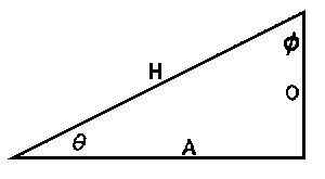
    In any right triangle, if we let
    Ø = the acute angle formed by the hypotenuse and
    the base leg,
    ø = the acute angle formed by the hypotenuse and
    the altitude leg,
    H = the hypotenuse,
    A = the side adjacent Ø and opposite ø,
    O = the side opposite Ø and adjacent ø,
    then sine of Ø = sin Ø = O/H
    cosine of Ø = cos Ø = A/H
    tangent of Ø = tan Ø = O/A
    cosecant of Ø = csc Ø = H/O
    secant of Ø = scc Ø = H/A
    cotangent of Ø = cot Ø = A/O
    also
    sin Ø = cos ø csc Ø = sec ø
    cos Ø = sin ø scc Ø = csc ø
    tan Ø = cot ø cot Ø = tan ø
    and
    1/sin Ø = csc Ø 1/csc Ø = sin Ø
    1/cos Ø = sec Ø 1/sec Ø = cos Ø
    1/tan Ø = cot Ø 1/cot Ø = tan Ø
       The expression “arc sin” indicates, “the angle whose sine is”…;
    like wise arc tan indicates, “the angle whose tangent is”…etc.
    See formulas in table below
    Known
    Values
    Formulas for determining Unknown Values of …
    A O H Ø ø
    A & O arc tan O/A arc tan A/O
    A & H arc cos A/H arc sin A/H
    A & Ø A tan Ø A/cos Ø 90° – Ø
    A & ø A/tan ø A/sin ø 90° – ø
    O & H arc sin O/H arc cos O/H
    O & Ø O/tan Ø O/sin Ø 90° – Ø
    O & ø O tan ø O/cos ø 90° – ø
    H & Ø 90° – Ø
    H & ø 90° – ø

  • Transmission Line Formulas

    Concentric Transmission Lines
    Characteristic impedance in ohms is given by

    R-f resistance in ohms per foot of copper line, is given by

    Attenuation in decibels per foot of line, is given by
    Where: Z
    ra
    d1

    d2

    f


    =
    ==
    =

    =

    =

    characteristic impedance in ohms,
    radio frequency resistance in ohms per foot of copper line,
    attenuation in decibels per foot of line,
    the inside diameter of the outer conductor, expressed in inches,
    the outside diameter of the inner conductor, expressed in inches,
    frequency in megacycles.
    Two-Wire Open Air Transmission Lines
    Characteristic impedance in ohms is given by

    Inductance in micro henrys per foot of line is given by

    Capacitance in micromicrofarads per foot of line is given by
    Attenuation in decibels per foot of wire is given by

    R-f resistance in Ohms per loop-foot of wire, is given by

    Where: Z
    D
    d
    L
    C
    db
    Rf
    f


    =
    =
    =
    =
    =
    =
    =
    =
    characteristic impedance in ohms,
    spacing between wire centers in inches,
    the diameter of the conductors in inches,
    inductance in microhenrys per foot of line,
    capacitance in micromicrofarads per foot of line,
    attenuation in decibels per foot of wire,
    r-f resistance in ohms per loop-foot of wire,
    frequency in megacycles.
    Vertical Antenna
       The capacitance of a vertical antenna, shorter than one-quarter
    wave length at its operating frequency, is given by
    Where: Ca
    l
    d
    f
    e
    =
    =
    =
    =
    =
    capacitance og the antenna in micromicrofarads,
    height of antenna in feet,
    diameter of antenna conductor in inches,
    frequency in megacycles.
    2.718 (the base of the natural system of logarithms).